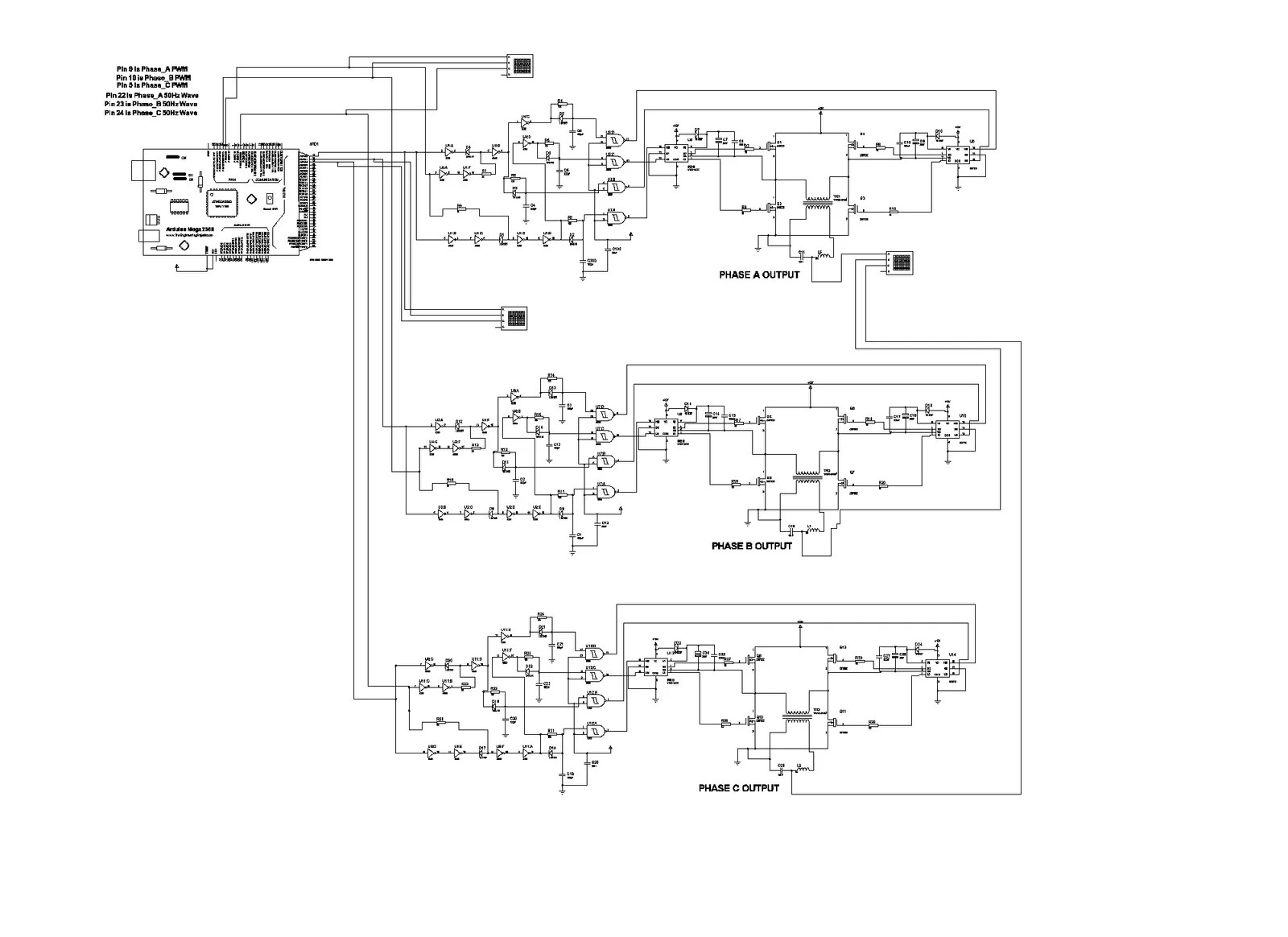
3 Phase Inverter Using Mosfets Circuit Diagram
Few days ago gohz made a 24v 2000w power inverter in home sharing some design schematics and circuit diagrams.
3 phase inverter using mosfets circuit diagram. The circuit below shows a 3 phase inverter inverter circuit stage using h bridge mosfets configuration which receives the phase shifted pwms from the above stage and converts them into corresponding high voltage ac outputs for operating the connected 3 phase load normally this would be a 3 phase motor. The tida 00195 reference design consists of a 22kw power stage with tis new reinforced isolated igbt gate driver iso5852s intended for motor control in various applications. This is the circuit diagram of 3000w power inverter 12v to 230v modified sinus capable to deliver about 3000w 230v ac output from 12v input. This is the inverter circuit for professional only.
This sg3525 inverter circuit is suitable for 100 watt applications. This article contains circuit diagram ic features working and video demonstration of the circuit. These modified inverters produce a square wave and these are not used to power delicate electronic equipments. Here a simple voltage driven inverter circuit using power transistors as switching devices is build which converts 12v dc signal to single phase 220v ac.
100 watt inverter circuit diagram parts list design tips. Inverters are devices that convert dc input supply to ac alternating current. They are also called power inverters. A power inverter or inverter is an electronic device or circuitry that changes direct current dc to alternating current ac.
The input voltage output voltage and frequency and overall power handling depend on the design of the specific device or circuitry.


