Inverter Battery Charger Circuit Diagram
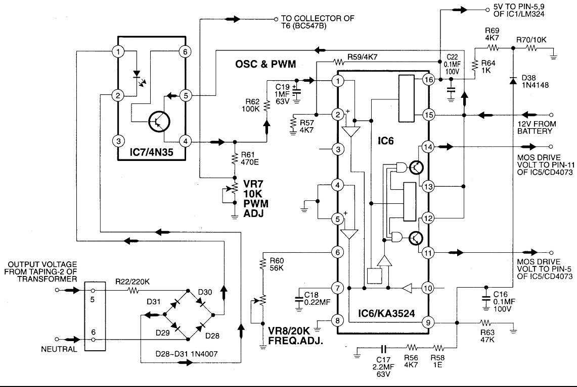
It will convert 12vdc to 220v 50hz.

Inverter battery charger circuit diagram. This is the circuit diagram of car battery charger which used scr 2n3896. If the circuit built and setup correctly it will safely charge at 10 amps and automatically regulate down to a trickle charge. This is the circuit diagram of car battery charger which used scr 2n3896. If the circuit built and setup correctly it will safely charge at 10 amps and automatically regulate down to a trickle charge.
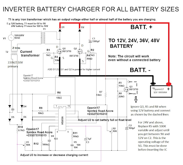
Working of battery charger circuit. The charging circuit is build around voltage regulator ic 7815 and two transistors bc 548. The main supply 230v or 110v is stepped down using a step down transformer and then it is rectifiered and filtered out. 100 watt inverter circuit diagram parts list design tips.
Inverters are devices that convert dc input supply to ac alternating current. They are also called power inverters. 12v battery charger circuit with auto cut off gallery of electronic circuits and projects providing lot of diy circuit diagrams robotics microcontroller projects electronic development tools. A 12v battery full charging circuit with simple diagram for rectifier is giventhe lead acid trickle charger circuit is explained with a rectifier.
Hi guys how are you today. This is inverter circuit 500w output.


