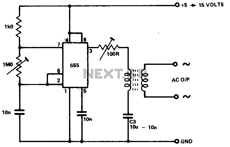
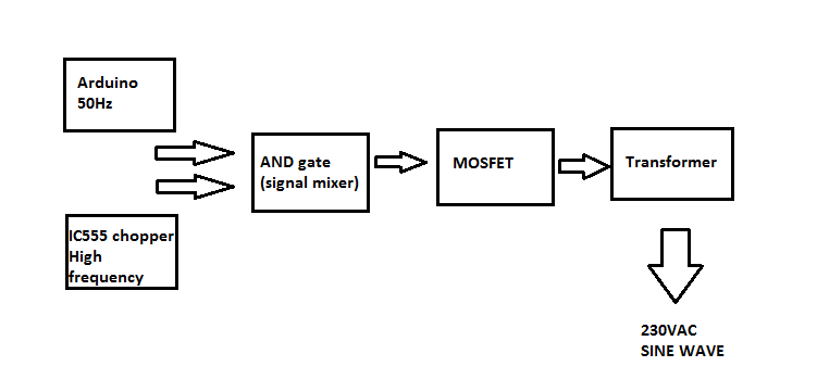
High Frequency Inverter Circuit Diagram
The ic sg3524 operates at a fixed frequency the oscillation frequency is determined by one timing resistor rt and one timing capacitor ct.
High frequency inverter circuit diagram. 100 watt inverter circuit diagram parts list design tips. Inverters are devices that convert dc input supply to ac alternating current. They are also called power inverters. Induction heating is a non contact heating process.
It uses high frequency electricity to heat materials that are electrically conductive. Since it is non contact the heating process does not contaminate the material being heated. Inverters are the device which converts dc direct current to ac alternating current and gives high woltage and current from low power battery source. This is inverter circuit 500w output.
It will convert 12vdc to 220v 50hz. You can build it easily and inexpensive. Because like working outdoors or to backup storage to use when necessary. Principle behind this circuit.
The basic idea behind every inverter circuit is to produce oscillations using the given dc and apply these oscillations across the primary of the transformer by amplifying the current. Simple low power inverter circuit 12v dc to 230v or 110v ac diagram using cd4047 and irfz44 power mosfet gallery of electronic circuits and projects providing lot of diy circuit diagrams robotics microcontroller projects electronic development tools. This 200 watt high quality power audio amplifier will give you top class quality for loudspeaker 4 8 ohm. Frequency range 20 20000hz voltage 24 36v with current max 5a.
Working of pwm inverter circuit.


