Pwm Inverter Circuit Diagram
Welding inverter is handy and runs on dc current.

Pwm inverter circuit diagram. Share on tumblr inverters are the device which converts dc direct current to ac alternating current and gives high woltage and current from low power battery source. Inverters are very helpful to operate electrical appliances during power cut or shortage inverters can be classified based on the output terms like square wave modified. Simple pwm inverter circuit diagram using pwm chip sg3524 gallery of electronic circuits and projects providing lot of diy circuit diagrams robotics microcontroller projects electronic development tools. Hi its my first time build an inverter neh thing is the circuit diagram of the pwm doesnt seem to make sense as it shows the ic with all sided pins while the one at the bottom and the one i bought is two sided and also it doesnt say as to the porality of the ic or where the lines to the mosfets come from.
Could you please grant me. 100 watt inverter circuit diagram parts list design tips. Inverters are devices that convert dc input supply to ac alternating current. They are also called power inverters.
Using the sg3525 pwm controller explanation and example. Circuit diagram schematic of push pull converter. A power inverter or inverter is an electronic device or circuitry that changes direct current dc to alternating current ac. The input voltage output voltage and frequency and overall power handling depend on the design of the specific device or circuitry.
Neon lamp inverter circuit. If you are looking for an option to replace conventional welding transformer the welding inverter is the best choice.
Pwm Inverter Circuit

Pwm Inverter Circuit Based On Sg3524 12v Input 220v Output 250w

Shows The Complete Circuit Diagram Of The Pwm Inverter Circuit Ic 3

Pwm Inverter Circuit 500 Watt Low Cost Circuits Diy

12v To 230v Inverter Circuit Schematic Using Pulse Width Modulator

Simple Pwm Inverter Circuit Diagram Using Pwm Chip Sg3524 Circuits

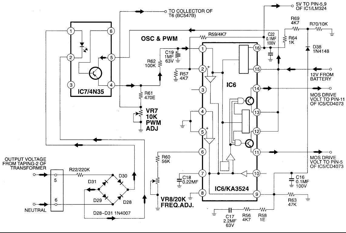
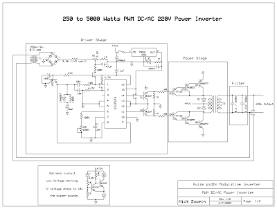
250 To 5000 Watts Pwm Dc Ac 220v Power Inverter

Pulse Width Modulated Inverter

250 To 5000 Watts Pwm Dc Ac 220v Power Inverter

Pwm Inverter

Pwm Inverter Circuit

Introduction Of Igbt Based Single Phase Pwm Inverter

Shows The Complete Circuit Diagram Of The Pwm Inverter Circuit Ic 3

Simple Pwm Inverter Circuit Diagram Using Pwm Chip Sg3524 Circuits

250 To 5000 Watts Pwm Dc Ac 220v Power Inverter
Mosfet Based 500 Watt Pwm Inverter With Solar Battery Charger

5kva Ferrite Core Inverter Circuit Full Working Diagram With

Low Power Square Wave Inverter Circuit Using Cd4047

Three Phase Voltage Source Pwm Inverter The Circuit Model Of A
Inverter 5000w With Pwm Pulse Width Modulator Learn Circuit Diagram

7 Modified Sine Wave Inverter Circuits Explored 100w To 3kva

Shows The Complete Circuit Diagram Of The Pwm Inverter Circuit Ic 3

Pwm Sinewave 5kva Inverter Circuit Electronics Circuit Projects

Selective Harmonic Elimination She For 3 Phase Voltage Source

Schematic Diagram Of Single Phase Full Bridge Inverter Circuit

10 Best Inv Images Electronics Projects Circuit Diagram Diy

7 Modified Sine Wave Inverter Circuits Explored 100w To 3kva

250 To 5000 Watts Pwm Dc Ac 220v Power Inverter

Block Diagram Of Spwm Generating Control Circuit For Three Phase Pwm

Sine Pulse Width Modulation Spwm And Its Working

Ic 555 Inverter Circuit Using Mosfet

Simple Low Power Inverter Circuit 12v Dc To 230v Or 110v Ac

Overload Protection Circuit And Low Battery Alarm Many Circuits

7 Modified Sine Wave Inverter Circuits Explored 100w To 3kva

Max724 5 Volts Dc Inverter Circuit Diagramcircuit Diagram World

How To Make H Bridge Using Ir2110

Figure 4 From Unipolar And Bipolar Pwm Inverter Semantic Scholar

12v Power Inverter Circuit Using 555 Timer Energy In 2019

Dc To Ac Inverter Card With Igbts

Simulation Of Three Phase Inverter In Simulink Matlab Youtube

Inverter Circuit Diagram 2000w Wiring Diagram

12v 24v Pwm Motor Controller Circuit Using Tl494 Irf1405

Selective Harmonic Elimination She For 3 Phase Voltage Source

7 Modified Sine Wave Inverter Circuits Explored 100w To 3kva

4 Pin Pwm Fan Circuit Diagram Wiring Diagram Document Guide

Figure 4 From Unipolar And Bipolar Pwm Inverter Semantic Scholar

555 Timer Pwm Generator Circuit Diagram

Sine Pulse Width Modulation Spwm And Its Working

Voltage Source Inverter An Overview Sciencedirect Topics

Space Vector Pulse Width Modulation A Technique To Mitigate The
